Get the sound
Here I would like to mention a few common modifications that are easy to implement and dependably change the sound. But you musst not expect too much. There are always nuances, which form the sound all together.
Often harp and guitar are equated and associated with low knowledge, the evidence about a test without reference and much self-confidence, this results in a tip on the Internet or in books that spread.
As an example, the rectifier tube. At the SE, it has no real influence on the sound. It only influences the power supply and lowers the voltage. This can also be achieved with a resistor, so why use a tube in a self-made amp and compensate it by larger transformers? If the rectifier tube developes "SAG" in larger PP amplifiers, then it is counterproductive for harp. The harp is not a percussive instrument, making it even more "spongy" brings nothing.
NFB - "negative feedback"
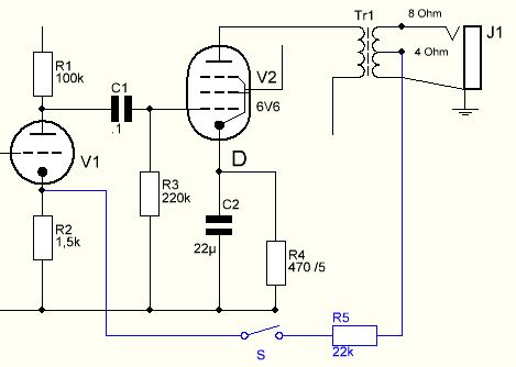
This feedback has nothing to do with the annoying whistling. The NFB loop carries the signal from the speaker via a resistor back to the pre amp, usually the second triode or the phase inverter. This coupling should dampen the distortions and resonances. It makes the sound a little dull and cleaner. Depending on requirements, you can now retrofit it with a loop or modify the existing one or even remove it. A switch can be installed to utilize both states. An unproblematic and profitable modification.
The value of the resistor is based on the respective diagrams of Fender. If an anode electrolytic capacitor exists, the negative feedback must be applied differently, just take a look at the diagram of the Champ AA764.
Remove high frequencies
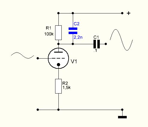
If you want to filter out higher frequencies permanently, you can do this with the aid of a capacitor. To place a capacitor from the signal path to ground often has other effects on the circuit that we do not overlook. It is simpler, to lay the capacitor over an anode resistor of the corresponding triode (I like to take the second).
The capacitor must be voltage-proof, the anode resistor has a few volts. You can thus easily calculate the cut-off frequency of the filter because no additional components are in the game.
For a better understanding, I have drawn the condenser to the right of the resistor, because there it works - after the tube. For the AC voltage of the signal, it does not matter whether they are diverted to the positive side or to ground, the power supply electrolytic capacitors are a direct connection to ground for these frequencies.

Circuit of the pre amp
The circuit of the input stage can be influenced by several ways.
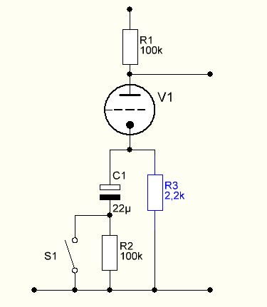
Increasing the cathode resistor puts our operating point slightly to the left of the linear region. Thus we get a little unsymmatrical signal that with a sufficiently large amplitude becomes distorted one-sided. We keep the dynamic, but get a little saturation to the sound. For a 5751 the 2,2-2,7k have proven. This replacement, I would only do at V1, apart from that remain as linear as possible.
The cathode e-cap can become switchable, whereby you have two usable gain levels. The picture shows the luxury version with a resistor which prevents cracking noises.
Of course, this can be done for each cathode, but empirically the switch pays only for V1. Otherwise, it is enough to decide either for or against e-cap.
Mismatch of the speaker
A mismatch to 100% is not tragic for a tube amp. So if we have a transformer, for example with 8 Ohm output and we take a speaker with 4 Ohm, the sound changes. Not always reliable, we do not know exactly how the other side of the transformer is adjusted, but you can check it out.

