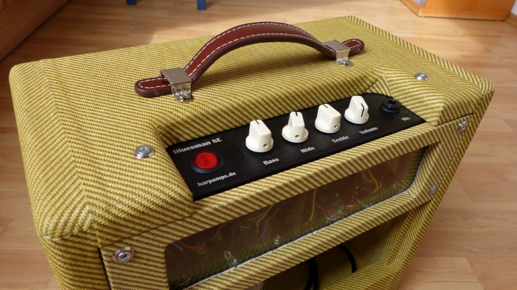
The Bluesman SE
This Amp is the successor of the Poor Bluesman. The essence of all SE amps that I have built and rebuilt. No voodoo, simple circuit constructed consistently. It can be set to be really clean, but also singing. A lot of beginners want more distortion, simply take an AX, mids up, treble down .... that's all. The development is complete, there will be no new version of the Bluesman SE. So, go for it!


Features
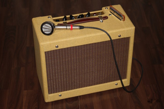
There is not much space left. A slightly larger enclosure brings a few more volume in sound. But there is a full tone stack, a gain switch and an adjustable line out. You can fix your FX in the back with a velcro and there are also jacks for looping and a 9V supply. The power amp got a 6L6 SE and makes about 15W of power.
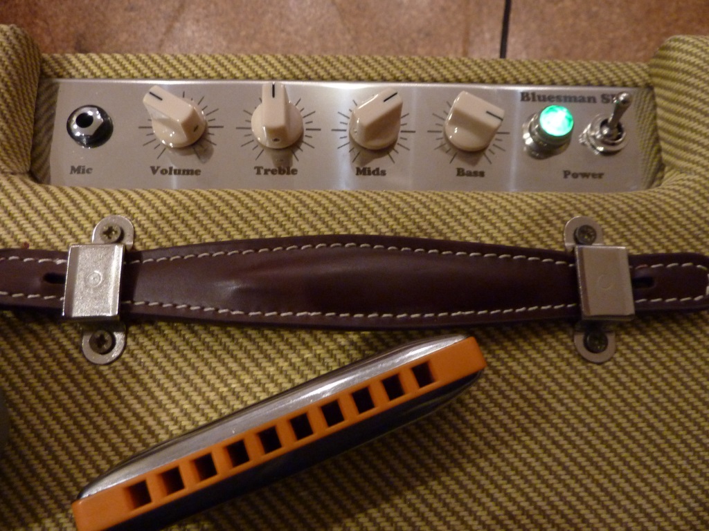
The common controllers, light and switch in one for saving space reasons. I know, coffee-machine, but it simplifies things considerably. Although some expect a "pilot light" adds more "vintage vibe", it makes sense. The amp weights 8.5 kg and is loud enough for most opportunities.
Sound
"Rocker" by Fritz
"Last Night" by Fritz
"Juke" has built a SE
More to come by Fritz
And a solo by Wolfgang
Ressourcen / Downloads
You can find some downloads here soon.
Considerations
A SE amp has its own sound, which sometimes is more accommodating for certain situations than the PP variation. But performance is immediately noticeable in disproportionate weight gain of the SE (single ended), so we are limited. What is the silver bullet?
Speaker
With 8" it may be too little volume. And 12" is large, too slow and prone to feedback, so we take a 10". As a Speaker, I first had an Eminence 1028K in my mind, but then prefered the WGS Veteran. This one has the vintage sound of Jensen, no annoying highs and works powerfully like some 12". A tonally very similar candidate would be the Weber 10A125O with a little less pressure and maybe more distortion in the lows. Also a good choice -.. but it does not fit in.
Transformers / Tubes
How much weight do I invest? How much power is worth it? The tube is almost given, a 6L6 will it be. The best solution seemed the T50 with 125DSE. But that would be an interim solution which is neither lightweight nor louder than 5W. So, 600g more ... T56 and 125ESE. Now I have appropriate anode voltage and 12V for gimmicks! Transformers, speakers, tubes, ... everything is on the way.

Features
I tried a lot and some got kicked. The 9V and a socket remained, so you can integrate a stompbox in the cabinet. For this purpose, a controllable and corrected lineout and a way to change the character in the pre amp and in the power amp. These switches can be designed fixed or can be varied in the action with trimmers. This may be quite useful. The wishes of the players are quite different.
The Board
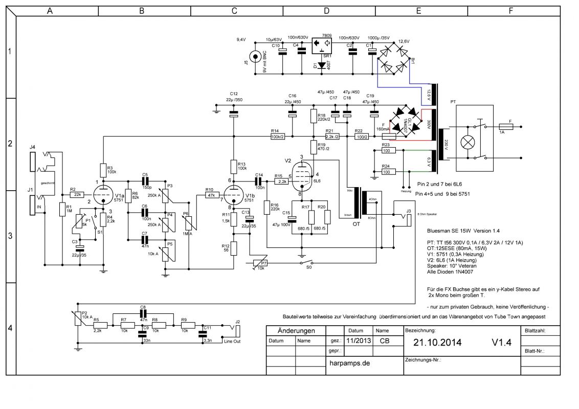
Because I see the features in a flexible way, here is an exemplary plan that everyone can customize for his own needs. It has evolved and can be taken as proven.
Version Update 1.6 at 04.2016: Historie: Plan V1.4/1.5
Mario made a parts list for the project. Use it to shop at TubeTown.
It still refers to the version 1.4 or 1.5, so omit both, the trimmer and a 4.7k resistor.

First you cut a board from 2mm hard paper mounting plate or glass fibre on 55x255mm (formerly 260mm, but this is close - there are no problems with the template). That works pretty good with the circular saw if you ensure that there are no vibrations. Then you print the image below - it must have approximately 55mm height - and tape it on the edges of the board.

Then you drill the holes with 3,2mm. In the picture I used a fixed template instead of a paper mask . There is no need. Even my boards are not tailored to the final length, so don't be surprised.
We redrill the screw holes with 3,5 or 4 mm, otherwise they will also be riveted because once the template gets removed, all the holes look the same.
In the picture, I drilled them afterwards.

You might take the 5mm rivets from any hardware store, but I prefer the 3mm rivets from a specialised shop, even if they are more expensive. I rivet on a beech log with a punch. Do not hit too hard, it could damage the circuit board. If you shake afterwards, nothing must rattle. That's enough.

Now, the components are soldered. Therefore, it is recommended to measure the values. Even if only one of 1000 components may be faulty, you have to look for it later on.

We put the electrolytic capacitor of the final stage cathode a little high, so it does not get fried by the resistors. The two 5W are designed generously, no need to worry.
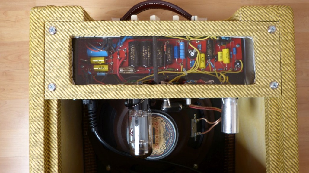
There are no connections or parts on the bottom. Thus, the circuit is always visible and you can easily perform modifications. If you look closely, you might recognize that the last power supply capacitor has only 10uF. Fits better and the capacity is appropriate.

This way we get a complete board in a short time. The capacitors in the 9V power supply are greatly oversized, but this way confusion is not possible and all parts can be purchased from any sender. The link to the parts list can be found above in the diagram.

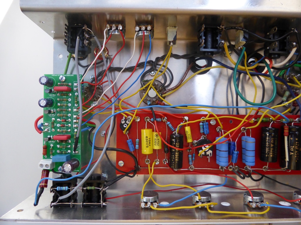
Mario has painted a very detailed plan for the wiring and kindly gave it to me for this webpage. The board is a bit bigger - the potentiometers are drawn from the front. But that does not matter - you even do not have to rethink, because the potentiometers are upside down in the final state.
In the new version, the trimmers are missing and the cables to the potentiometers are in contrasting colors. Also the connection of the mass of 9V and tube amplifier is separated as it is in the plan. The connection is not necessary and can produce ground loops on the FX socket.

Chassis and wiring
The chassis is usually the biggest hurdle for hobbyists, especially if a professional look is desired. I used 2mm aluminum that is laser-cut and folded, then anodized and labeled with the laser. The costs are around 100 € per chassis. The free drawing can be requested, please contact us.

Cheaper would be a simple aluminum housing and a faceplate. This can be produced by a laser or a milling machine, I used a milling machine for the component in the image. You can also request a free drawing by mail.

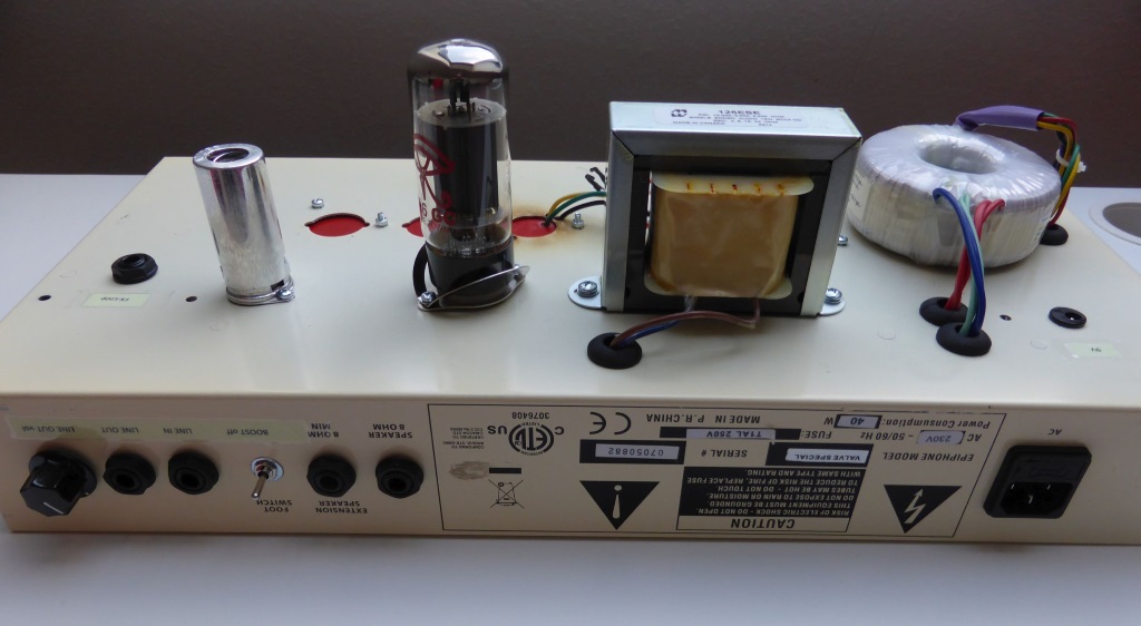
Here, the rear view of the transformer assembly. The red mark in the upper picture shows the ground point, the anodic coating isolates, so grind away carefully. The red circle on the right marks the position of the transformer. You see the screws of the board. These may not be below the coil. If required, mill with a 90 ° countersink, using a M3x10 countersink screw. This fits properly then.

The board is not in yet. The screws only hold the spacers. Now you can mount the transformers. The bushings must be secured with rubber bands. At this stage, I would check whether the chassis and the speaker fits.

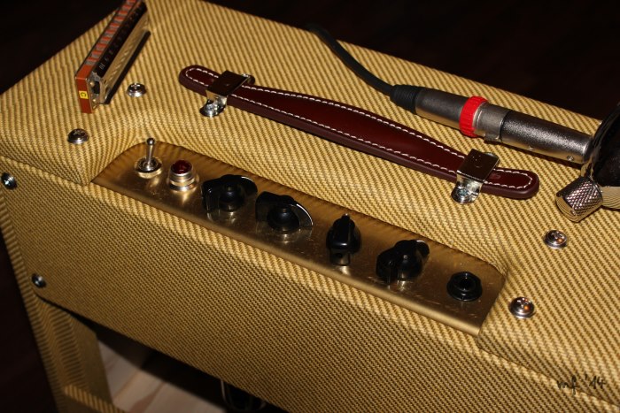
Now the rest of the hardware must be installed. Prevent the lamp, the 9V socket and the fuse holder from turning. If necessary, remove the anodic coating and place the suitable lock washers under the potentiometers. Here still without cable.

Now wiring the EQ. I only use silicone braid, which is nice to work with and you can use a soldering iron without melting anything.

Now with grid resistors and the FX socket, which interrupts the input. Do not forget the connection to the socket. As you search later on when nothing works .... because against expectations, the amp is not silent but very quiet then.

Connect the switch properly so the lamp only lights up if it is ON.

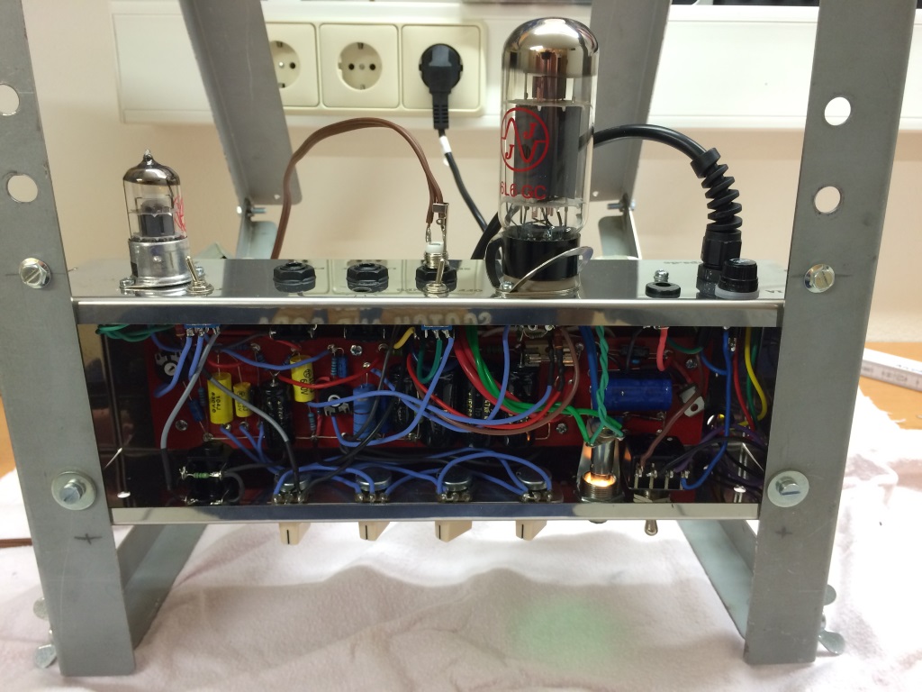
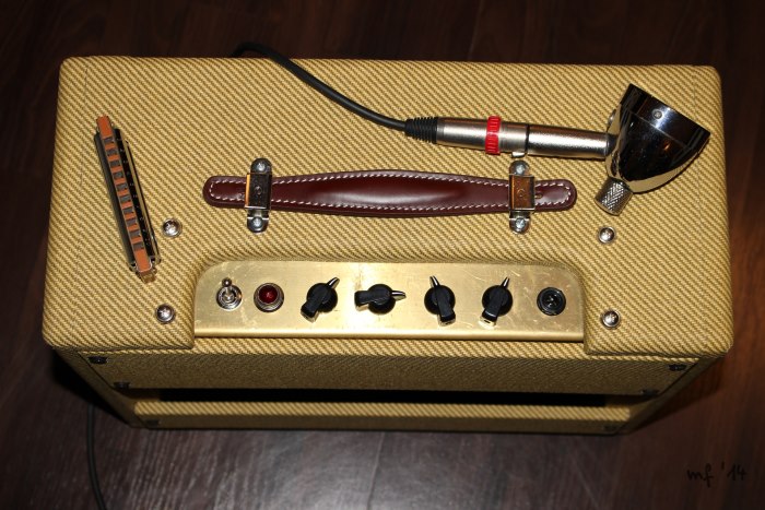
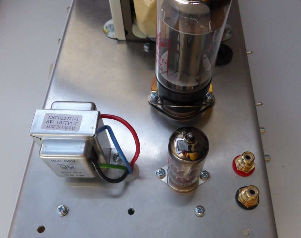
The output tube. You do not see much, the image is on the head by purpose. But maybe it solves a problem. The two 100 ohm resistors for example center the heater to the cathode - not to ground.
I always mark Pin 2 and 7 (heating) for not getting confused. You can see it in the picture.

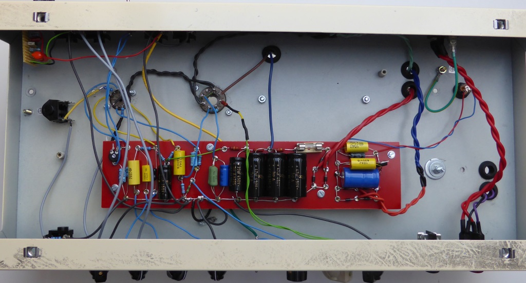
The result should look like this. Do not get confused by the different colors of the boards, I always forget to take pictures. Later on, matching wooden parts are screwed, do not leave it open in no case. A chassis with welded sides is more expensive and you can not reach the screws of the transformer after the installation of the board (use hexagon, not Allen).

This is the labeled bottom part.

Building the cabinet
Building cabinets is fun and saves money. The result is beautiful, light and resistant. And especially individually. Here I describe my cabinet, which is designed for 1x10" and compactness. Mine is 34 cm wide, 36cm tall and 21cm deep. 10cm wider would surely be good for the sound. Even more does not help.
Because the front is inclined:
- Side 19cm x 21cm / 34cm tall
- Plate top 32cm wide and 19cm deep
- Plate bottom 32cm wide and 21cm deep
- Slats front 2cm x 4cm x 32cm with bevel joint
- Slats back 7cm x 32cm no bevel joint
- Cover back 12cm x 31,5cm no bevel joint
- Baffle 31,5cm x 29,8cm tall

Since the thickness of the plates vary, you always have to measure and recalculate. Here are two versions of 9mm.
")
After cutting the 19mm plates I cut the angle of the side parts. The slopes are about 4°, I draw the 19cm and 21cm on the side panels and place the saw (use a long ruler or a straight bar ....). The stop block prevents slipping.

For the bevel of the slats, I put the blade to the actual angle formed by the side panels. In this case, almost 4°.

Now cutting all plates with the appropriate angle. For this purpose, the material must be already prepared. Instantly mark each oblique side, you can hardly see it in 9mm.
Then gluing everything, in the picture the bottom side.

I used 19mm laminated wood and 9mm multiplex and each screwed twice. Gluelam can only be glued poorly on the front side, saw tines, use no lamination, or use multiple screws. After the installation, change the angle if necessary and really let dry.

Now the cutout comes in. The corners are drilled with a 35 Forstner, thereby clamp a piece of scrap underneath so nothing gets frayed. Then use the jigsaw and if necessary plaster with a file. You can also make a template .... but just for once? Rather not.

When milling the edges, the cutter can rest on the side parts and you mill in the opposite direction. Leave the rear corners of the chassis pointed!
You can also use the plane to pull the corners of and round grinding them, if you do not have a circular milling machine.
I drill the mounting holes for the baffle board into the Cabinet with "30mm in, 14mm down" and with a 5mm wood drill. I've got a template that pays.

Now it comes to the "baffle", the dimensions can be found in the picture.

So that the clothing does not rattle, just put slats on the board. I use 3mm x 20mm. For the screw holes, I hammer in M4 nuts. Sinking is not required. Suitable screws would be M4x16. Then everything is dyed black so that nothing shines through. Paint the screws at the top with a black marker.
Then I stick the board with clamps (through the hole of the Speaker, do not forget to center) firmly and drill the mounting holes through. This way there will be no dirt later on.

Stringing takes a little practice. I start in the middle, go to the corners ... a matter of feeling. Stapling with 8mm brackets. A proper staple gun is advantageous. I also staple up and down on the front - works better for me.

The Tweed Clothing
Tweed is easy to work with and it's robust. I seal up... well, that's the wrong word... I paint a few layers of darker shellac on it. That looks good, but also adopts patina very quick. I think this is an advantage, who wants to look like a beginner :-).
The edge trims make a lot measurement unnecessary. On the photo, you can see 11cm on the wide strip, later maybe 12cm ... which does not matter with the SE. The angle serves to cut the tweed of the side parts later at a distance of 32mm. Do not use the hairdryer too long. Just make the cloth a little soft when stringing.

The Tweed is not always cut according to the sample. This should be checked at least.

Here is a possible pattern. Cut this way, the pattern runs from left top to right bottom. The numbers are the margin widths. I have taken the areas directly from the cabinet by putting it on top. The rear cover was missing and therefore 3cm margin on the edges where enough.

Paint the tweed and then the wood, thin but complete - let dry slightly - do not press too early, for it does not hold very good and you might get in trouble.

Put the case on the tweed - adheres pretty good!

Turn around and blow dry evenly, pull ..... let it dry slightly.

First, make the 4 vertical cuts.

At the corners, I first cut the vertical part near the top. Then I flap the horizontal part over it and cut a little further down through both layers. Always cut from the corner. Use a sharp knive! Use a new blade for cutting and for upholstering again.

Remove overlap in the middle. No shredding.

Apply glue everywhere, ventilate, press on with a hairdryer. Slap on the corner with the palm until everything is nice and even. Maybe recut on the cutting edge and remove strips. It's that easy.

Cut the overlap with the template (32mm).

Put the cabinet on the floor. The Tweed is as wide as the inside width. Coat the overlap and wood with glue - ventilate - press on.

Turn around and glue the rest. In my opinion, that way makes it quite easy to stay even.

It goes the same with the top cover, only the back is more difficult. Once you have glued the front, draw a bow of the cut. Now cut from the center in 45°. Put a 18mm slat at the corners and cut at a 45° angle (with the 18mm distance from the corner). This must be reworked later, so do not dawdle. Because of the cuts, the tweed is not very stable. First glue at the edges, then go to the inside.

The corners can be filled differently. Fender glues stripes underneath in a wild way. This is a little bumpy. I take the leftovers from the previous step.

I hope that helped. The rear cover should not raise troubles. It's better than you think. I tested glue, spray adhesive and Pattex. The Tubetown glue (Tolexkleber) is the best. And always ventilate!

Applying shellac is a matter of taste and experience. I use a darker shellac and dissolve it in spirit ... I have no mixing ratio, I always look for shellac on the ground and the glass should be as full as possible. I would start with 2cm shellac in a 200ml glass that is about 1/2 to 3/4 filled with spirit. The sauce should look rather dark while still flowing fine. The picture shows the consumption for one paint (what is missing from the glass). You should not get into the mush on the ground with the brush. Only make holes in the tweed after the shellac, they interfere. Use screws as stands.
Do not paint too wet. If you have paint drips or little dark "lakes" (which is normal) .... do not try to distribute it with a brush but absorb it with a cloth or sponge. Be quickly, alcohol evaporates quickly. The first painting is the most critical but do not panic when it is still slightly stained or show strange structures. From there on, it's more a painting and wiping.
If you cannot open the glass anymore because it is clotted, heat the lid with a hair dryer briefly (or with a burner - but then only a few seconds and be careful). The gentler method would be to turn the glass and pour spirit into the groove of the lid.
Approximately 3 coats, with one hour of drying time in between, give a beautiful shine. Should it become darker, more coats. If it gets too dark, take bright shellac.

Marios version
Mario, also known as the author of the harpbook www.harpbuch.de, was the first who recreated the SE.
Good for me, because I roughly draw exact plans (because I know what I'm doing and what has to be done...), but not everyone can follow this mess. But Mario did not give up and questioned any unclear points until a universal plan came out.
See his nice pictures and download the german report:
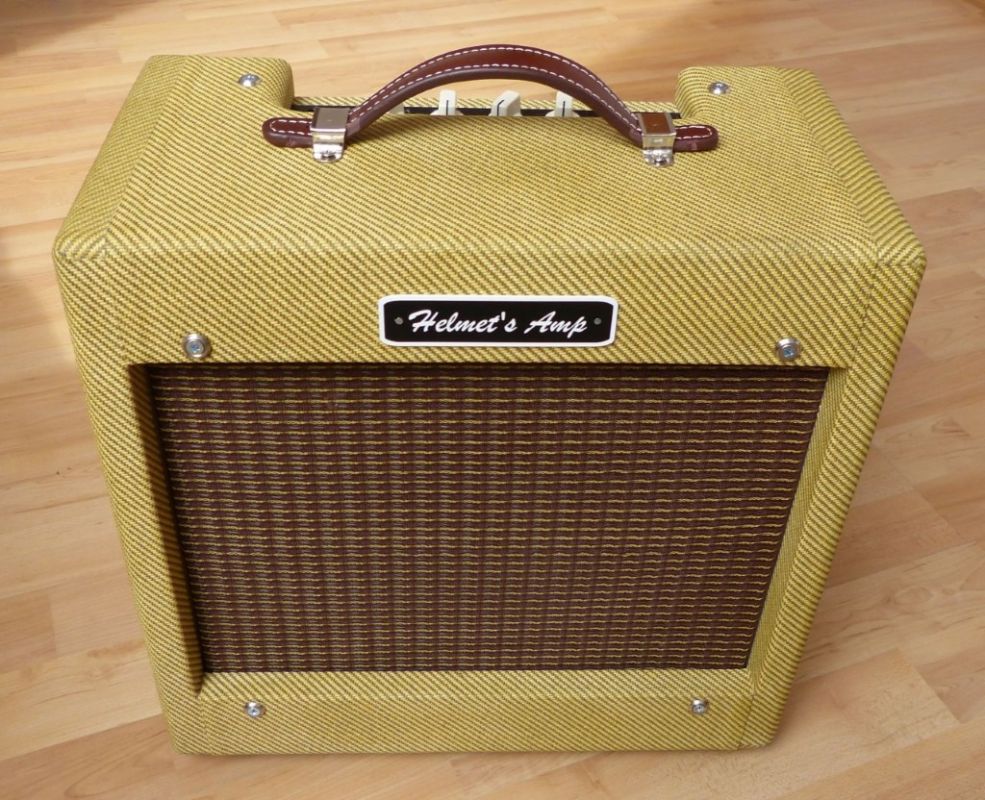
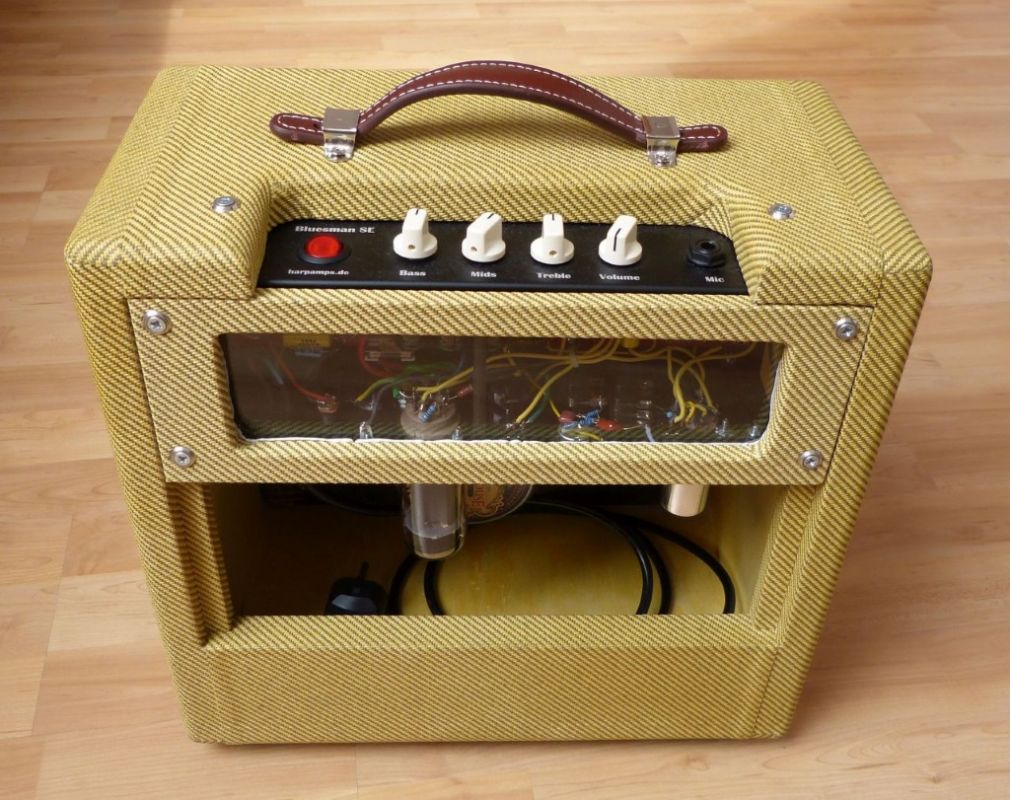
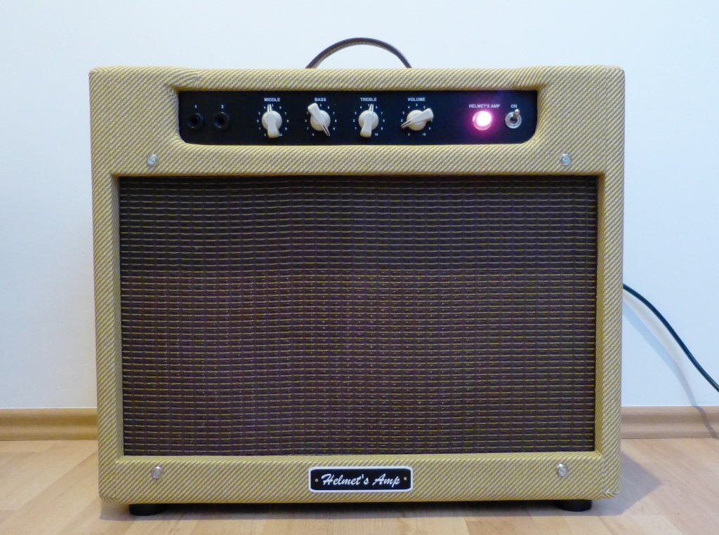
Helmuts version
Almost simultaneously to Mario, Helmut has built a SE. The chassis is "original", the rest is his own work. Here the pictures:
The second SE by Helmut
Shortly after the first one, a SE with Reverb and parallel output stage tube ...

and the next SE
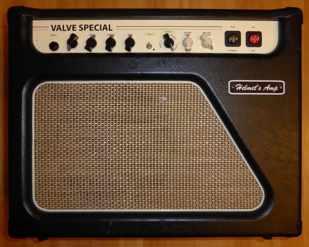
This time in the cabinet of an Epiphone. Including some gimmicks.
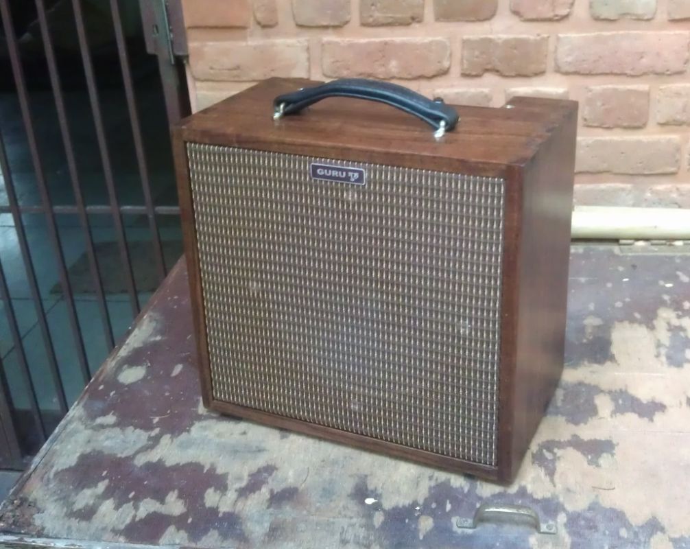
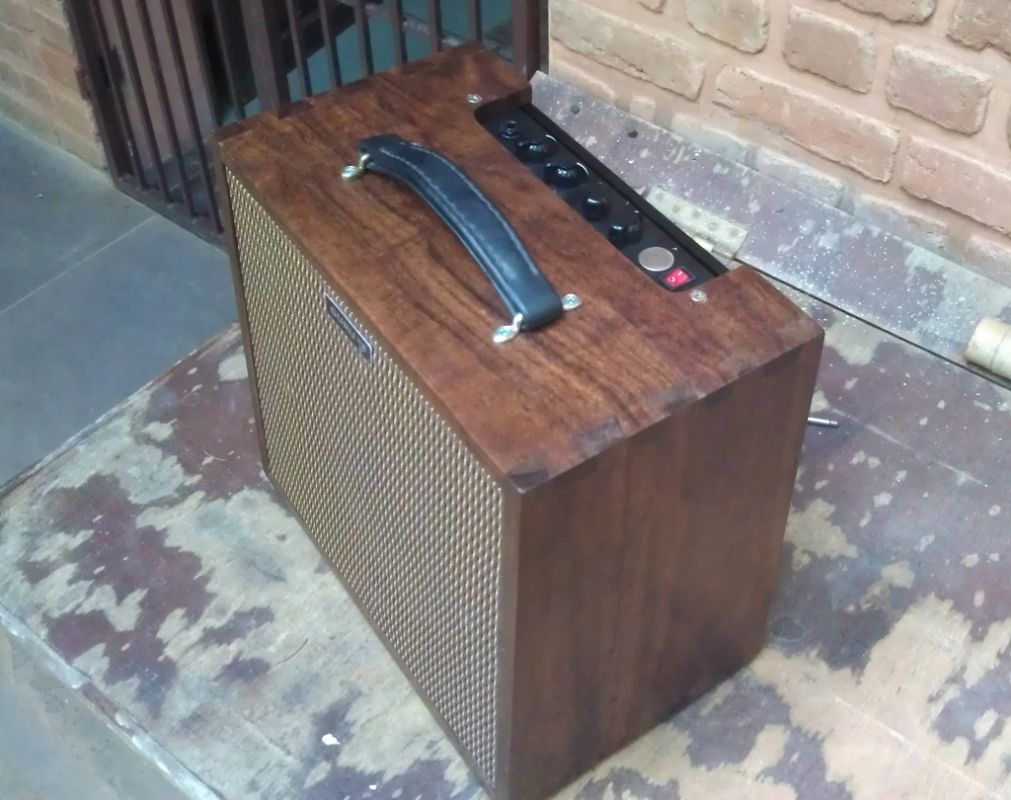
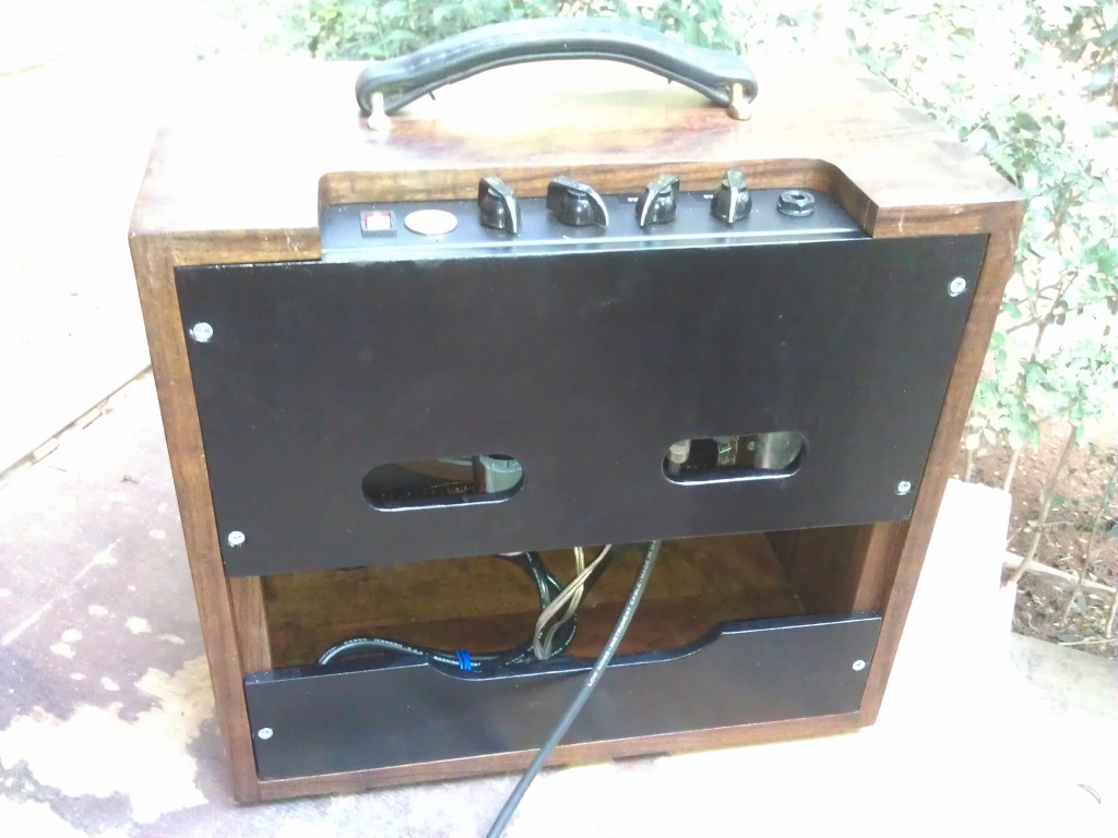
Ingos version
From India, pictures of Ingos replica reached me:
The Bluesman SE is finished. My friend "Guru Amp" has put together the electronics and a carpenter built the cabinet. Everything under different conditions than in germany. The sound is great and also the "look" has become very beautiful. A few minor things are not done yet. Labeling the buttons is difficult, I might do it with a special pen or engrave it eventually. The rear must be closed because of the Geckos around here, so I'll probably build a case someday.
Christians version
After meeting Christian in Traun 2015, I got some pictures of his SE.
Unfortunately, they got lost.
I have a picture of his second work, the SE for Hubert Hofherr.
To be continued...

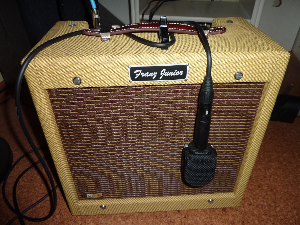
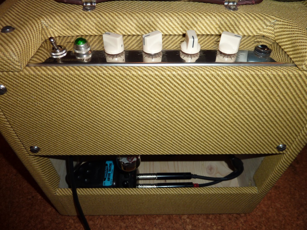
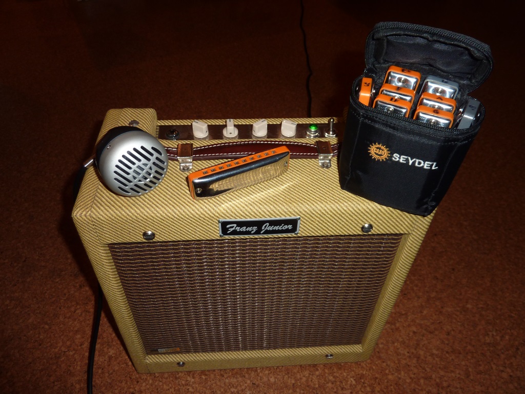
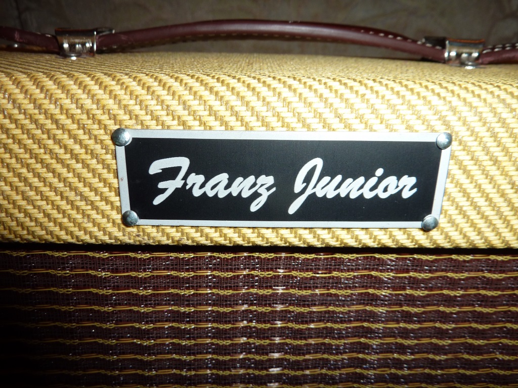
Franz' version
A nice work by Franz-Josef (mechanism) und Christian (electricity) from the Münsterland. What really impresses me is how the iron sheet gets perforated first and then folded. And then everything fits - and it is steel, not aluminum. As a tool-freak you can see many details.