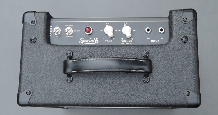
VHT Special 6
After all the hype about Epiphone and the Harley Bentons, there's a bright new star now that sounds pretty reasonable. But even if you change a lot in this mod - it's a good base.
This mod brings more power from the transformers, expect about 10W. That does not make it much louder, but there's a little more energy for the deeper tones.
The manufacturer kindly gave me the data of performance of the power transformer. We have 100mA at 275V and 1.25A at 6.3V. Thus, the transformer is designed well. If you do not turn it on forever, as per VHT you should be able to use 6L6 and even KT66 or EL34. But the risk remains with you, I just trust the 6L6 which do not need much heating.
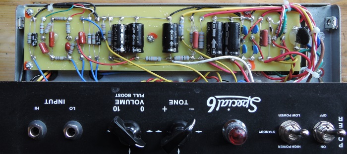
The circuit is not soldered in a nice way and there was a lot of smeared glue, but the components are OK. Caution, the wires are partially crap, do not move them unnecessarily. The circuit diagram can be found on the manufacturing side - Mods desired.
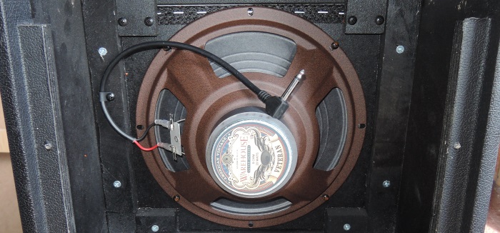
The built-in speaker is not the first choice for harp. I take the WGS Veteran 10". Here changing the speaker saves weight, at least 1.15 kg.
The replaced speaker has 8 ohms. If you only replace the speaker, you should disarrange the connection of the internal speaker (whereat the mismatch can also sound better). If you replace the tube with a 6L6 (as we do), you do not need to do that.
The changes are tested. In this version of the manual, I limit myself to specify only one value at a time. Of course, also other values are possible or reasonable, but the clearness suffers from the many additional explanations.
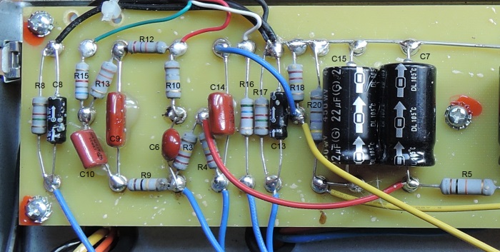
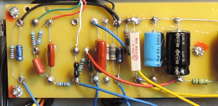
The cathode capacitors C8 and C13 have 4.7uF which is a bit too little - changing it for 22uF/25V brings an audible fuller tone.
The exchange of the first cathode resistor promises improvement. We change R8 to 2.2k.
The coupling capacitor C14 is very small with 4,7n, instead we take 100n / 400V.
R3 and R4 are the anode resistors. They become replaced by 100k.
We replace C6 with a 150p / 400V and R9 with a 82k resistor. I prefer this here in the description, because we just solder around this point.
We change R20 with 270 Ohm / 5W to give a little more power to the 6L6. C15 is already at the limit with the new value of R20. A 220uF / 63V takes us on the safe side, 47uF would also do.
Update 01.04.2016:
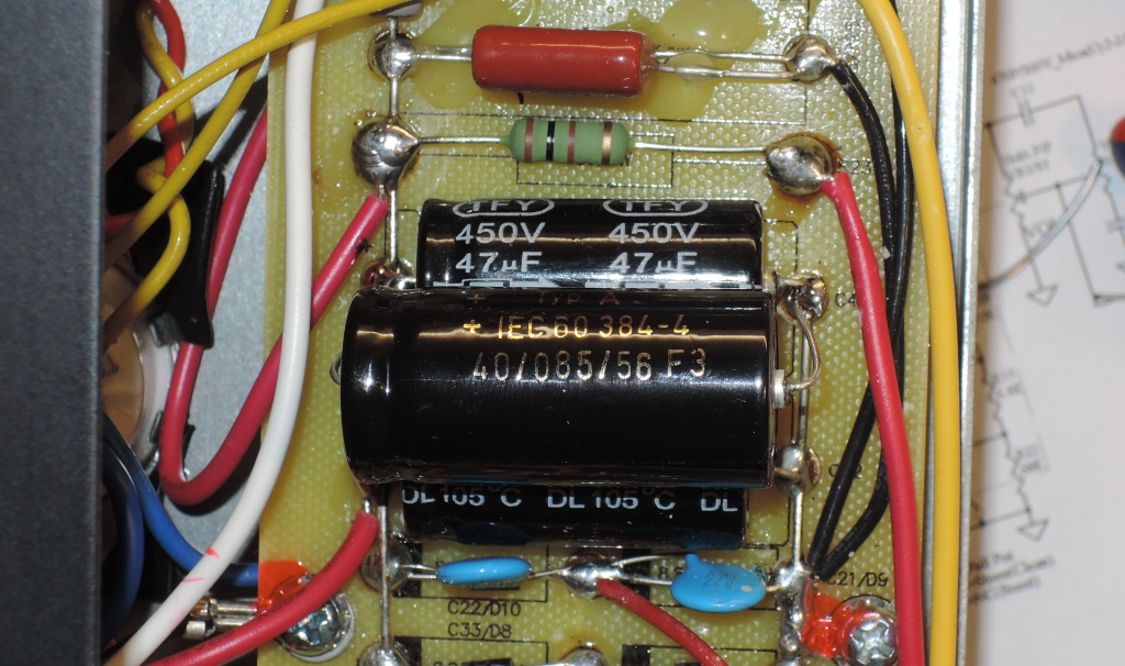
Therefore change R24 (according to the plan, because on my board it says R23) for a 100 Ohm / 2W type and double up the capacity by soldering a second 47uF thereafter (to the left). Then we have about 80mA in OT and 25W power loss at the 6L6, that fits.
We can increase R5 in order to reduce the voltage of the preamp, 100k / 2W is a common value.
We locate R10, R12, R13 and R15, which is the tone stack. For R13, solder in a resistor with 220k. This corresponds to the bass control turned up. R15 we replace by 3,3k. This adjusts the midrange, here we set the lower value. This value depends on the playing style and the taste very much.
R12 and R10 adjust the treble and are replaced by the potentiometer, get rid of it.
At the top left we see a shielded wire with multiple cores. Now we move the red wire one rivet to the left (to C9) and the white wire two to the left and one down (to C6).
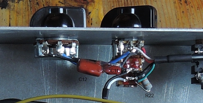
We pinch off the two capacitors C11 and C12 and the blue wire at the soldering points as close as possible. Then remove the cable tie that secures the cable to the jacks.
When slightly lifting the cable, you can replace the resistor R22 through a 3,3k. This brings an appropriate mid thrust.
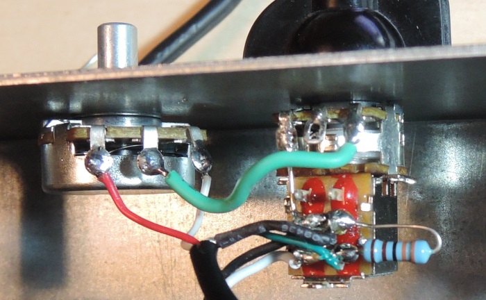
Remove the tone potentiometer. Now we take a 24 alpha potentiometer with A250k, break off the pin with flat-nose pliers and insert it. The button does not fit? Having a chicken head button with 6.3mm hole is advantageous.
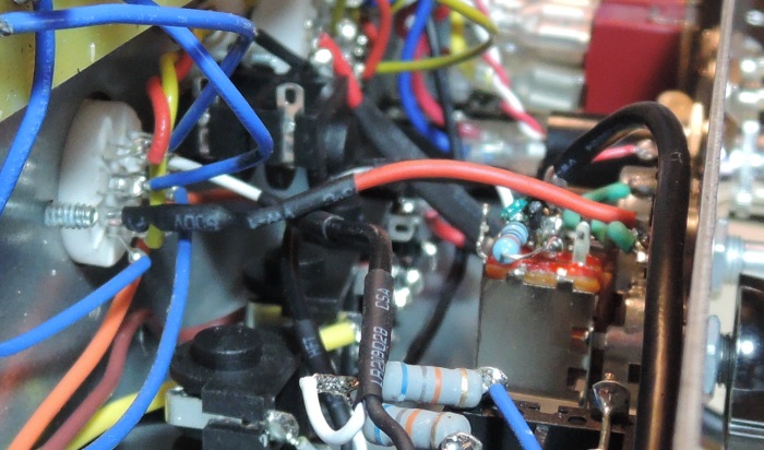
Now unsolder the red and white cable from the volume potentiometer. The heat shrink tube and the insulation must be removed a little, so the cables can get to the new tone potentiometer. Turn it a little to the volume. Solder the white wire to the right and the red one to the left side of the tone potentiometer. Another cable (here green) connects the right pin of the volume to the middle pin of the tone potentiometer.
R16 is no longer in use, but can remain on the board. The existing blue cable leading to the tube has to be removed.
At the newly available space on the tube socket we solder a 47k that we connect with the middle pin of the volume potentiometer (red cable). The resistance can be fixed with a heat shrink tube.
Now put in a 6L6 and a 5751 .... ready for take-off. That was already a lot of stuff, if you look at the pile of removed components.
The result is pleasant, it's a simple Bluesman SE. If you want the dark sound of the US hobbyists, solder a capacitor with 2.2 or 3,3n / 400V over the second anode resistor.
