Laney Cub 10
The Cub10 is a low priced tube amp that is well suited for a conversion into a harpamp. Some people play it "out of the box", but they can either deal very well with it or do not require much volume.
The complexity for this device is slightly higher than it is with the Champ-types, but it really pays. Fortunately the Laney is already available for a long time, I hope it stays that way. In the gallery, pictures of the old and new generation, easily to recognize by the clothing and the speaker.


The modification
It starts with the disassembling of the chassis, do not forget to disconnect the speaker cable before you start. Then loosen the potentiometers, remove the tubes, unbolt the three screws of the board, unbolt the 4 screws of the final stage versions. Unscrew the lamp inside, disconnect the thicker cables from the transformer, disconnect the input and disconnect the thin cable from the output on both sides. Now, you can take out the two circuit boards and remove all other connectors. Do you remember where the input jacks were connected to? We will need them again.
First of all, bridge the large yellow PTC, which limits the heating power. But this often causes problems, so we take it out of the circuit (of course at your own risk!). It's enough to connect the two contacts with a wire (not too thin). Should this lead to more hum, just regulate it with the trimmer right next to it.

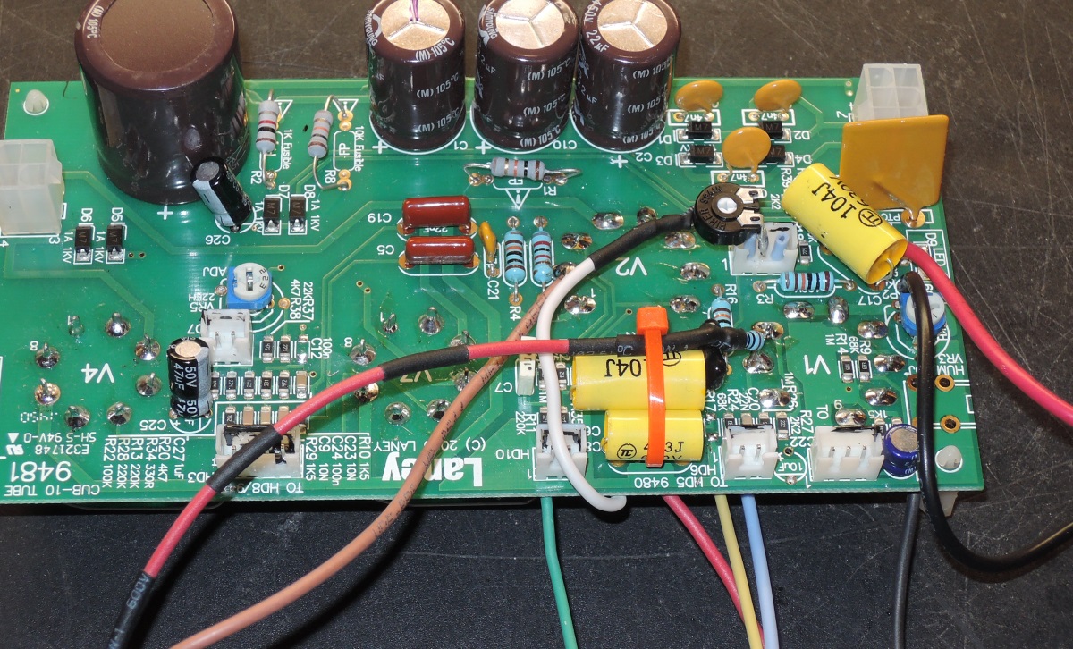
Now we remove many components. The board is well labeled, but for your convenience you can find all parts in the picture again. Just recount afterwards. C8, C6, C3, C22, C11, C17, C7, C12 (SMD) and R5, R6, R17 (all SMD).
Solder the SMD at both ends gently, then just push them away. The board can be soldered very well.
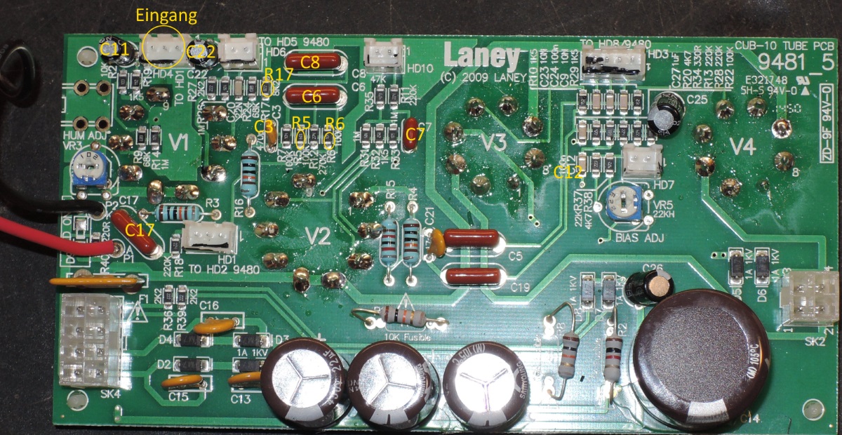
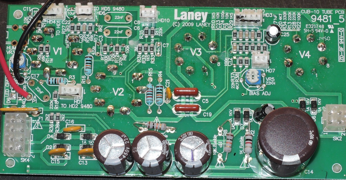

Now solder in the capacitors and the trim potentiometer. It's more easy by pinching off the strap of the connecting link. Here the components and values:
C3: 150p / 500V, C6: 100n / 630V, C8: 47n 630V, C11: 22uF / 25V, C17: 100n / 630V, C7: 100n / 63V, trimming potentiometer: 10k
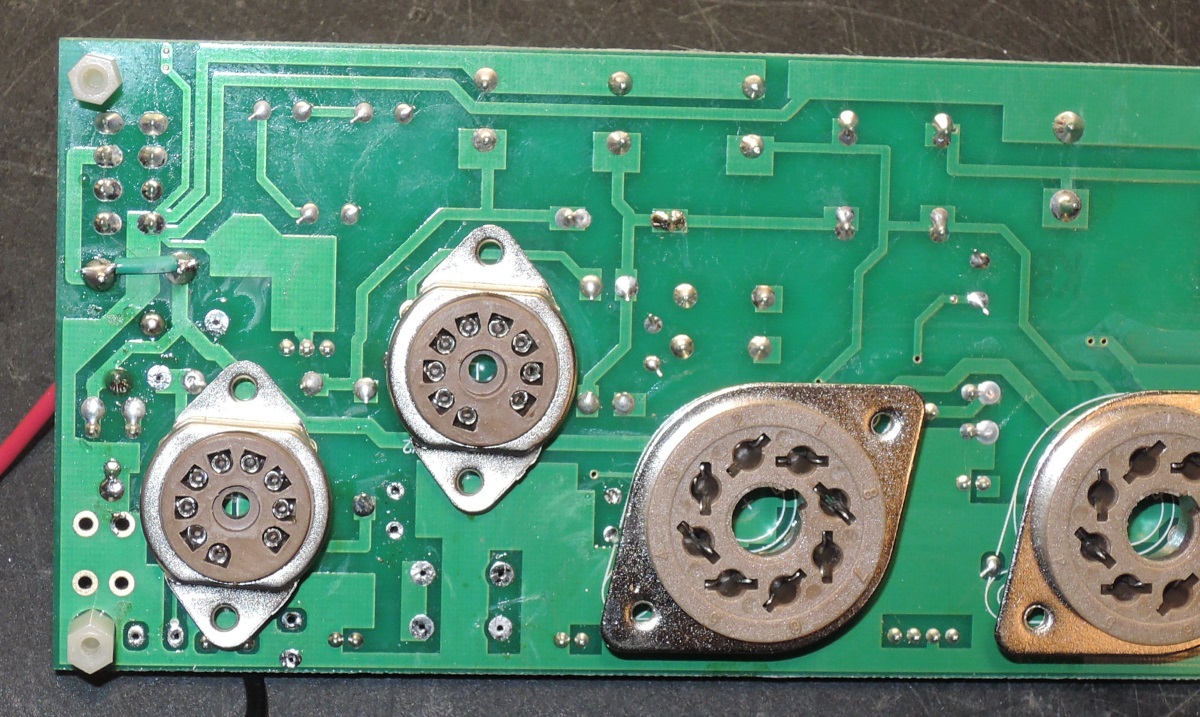
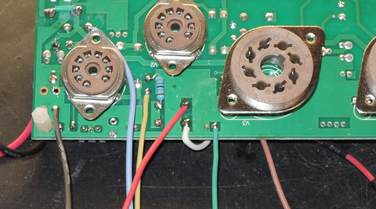
Now solder the 470k resistor and the cables to the back as seen in the picture. The colors have no meaning, they just ease the recovery. The green wire is soldered to the right contact of the connector, just as you can see (slightly covered by the fitting).
On the front, solder the white wire to the trimmer and the brown wire to the pin 2 of the tube V2. In the end, the 10k resistor is soldered on pin 2 of V1. Ensure it against mechanical strain.
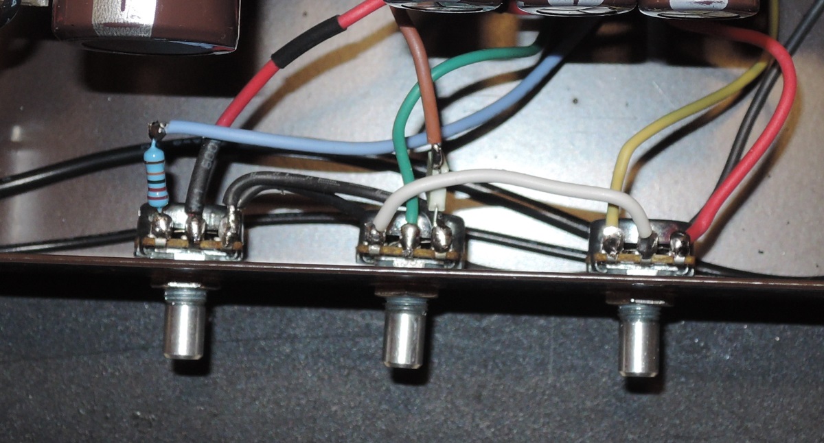
The wiring is not difficult. First the black wire to Pin1 of the gain potentiometer (500kA). Take another black wire and connect Pin1 of the gain with pin 1 of the volume potentiometer (1M A).
On the gain potentiometer at pin 3 solder a 220k resistor and then the blue wire. At pin 2 solder the black/red wire.
At the pin 1 of the volume potentiometer, which is already grounded, solder a 100n/63V capacitor and then the brown wire. The green wire is on Pin 2 and another white cable connects pin 3 of the volume with the pin 2 of the tone potentiometer (250k A).
At the tone control solder the yellow cable to pin 3 and the red to pin 1. It can all be seen in the picture.

A few more things to say ...
The bias current can be turned down a little, as preamp tubes AY in V1 and AT in V2 are quite appropriate and as a speaker of course my Veteran.
Set the trimmer we built in to 9-10 am, which is the midrange controller of the tonestack.
The amplifier now is as loud as the Bluesman SE. Sound can not be described, but that sounds quite decent.
